🔬 Fundamental Concepts of Exergy Analysis
Applied to Nuclear Reactor Thermodynamic Cycles
This page introduces the conceptual foundations of exergy analysis, illustrated throughout with examples drawn from the nuclear power plant cycles studied in the book. The content corresponds to posts A1, A3, A4, A5, and A6 of the companion LinkedIn series.
⚡ Energy vs. Exergy: What is the Difference?
👉 We often hear that a nuclear reactor has an efficiency of 33 %. But 33 % of what, exactly?
The energy efficiency of a reactor measures the fraction of heat transferred to the coolant that is successfully converted into electricity. For a standard PWR, this is around 33 %. For the Flamanville EPR, it reaches about 36 %. This is the energy balance: useful electrical power divided by the total heat input.
However, energy efficiency tells us nothing about the quality of that energy.
Thermodynamically speaking, one joule of heat at 300 °C and one joule of heat at 30 °C are energetically identical. Yet the former can produce far more work than the latter. This is precisely what exergy (denoted Xh) measures: the fraction of energy available for conversion into useful work relative to a reference environment (here, T₀ = 15 °C).
The exergy of a heat flow Q at temperature T is given by:
Xh = Q × (1 − T₀ / T)
- At T = 300 °C (573 K): Xh/Q = 1 − 288/573 = 0.50 → 50 % of the heat is theoretically convertible into work
- At T = 30 °C (303 K): Xh/Q = 1 − 288/303 = 0.05 → only 5 %
This is why raising the coolant temperature is not just about boosting energy efficiency — it is fundamentally about improving the thermodynamic quality of the heat supplied to the cycle.
The exergy balances presented in this section rely on this definition. The source temperature Tk varies across reactor designs — from ~283 °C for the VVER-70 to 699 °C for the AGR Hartlepool — reflecting the different types of heat exchange involved (see the section index for the full convention).
🔴 What is an Irreversibility?
One of the major differences between an energy balance and an exergy balance is that the latter reveals what we call irreversibilities.
In a thermodynamic cycle, anything that involves friction, any heat transfer occurring across a temperature difference, or any expansion without producing useful work destroys exergy. This is an irreversibility.
Every component receives exergy resources and generates exergy products. Its irreversibilities are equal to the difference between the two:
I = Xh_resources − Xh_products
For instance: a turbine receives steam with an exergy of 100 kW, supplies 85 kW of shaft work, and leaves 8 kW of exergy in the expanded downstream steam. It therefore destroys 7 kW of exergy — regardless of the underlying physical causes (friction, leaks, internal turbulence).
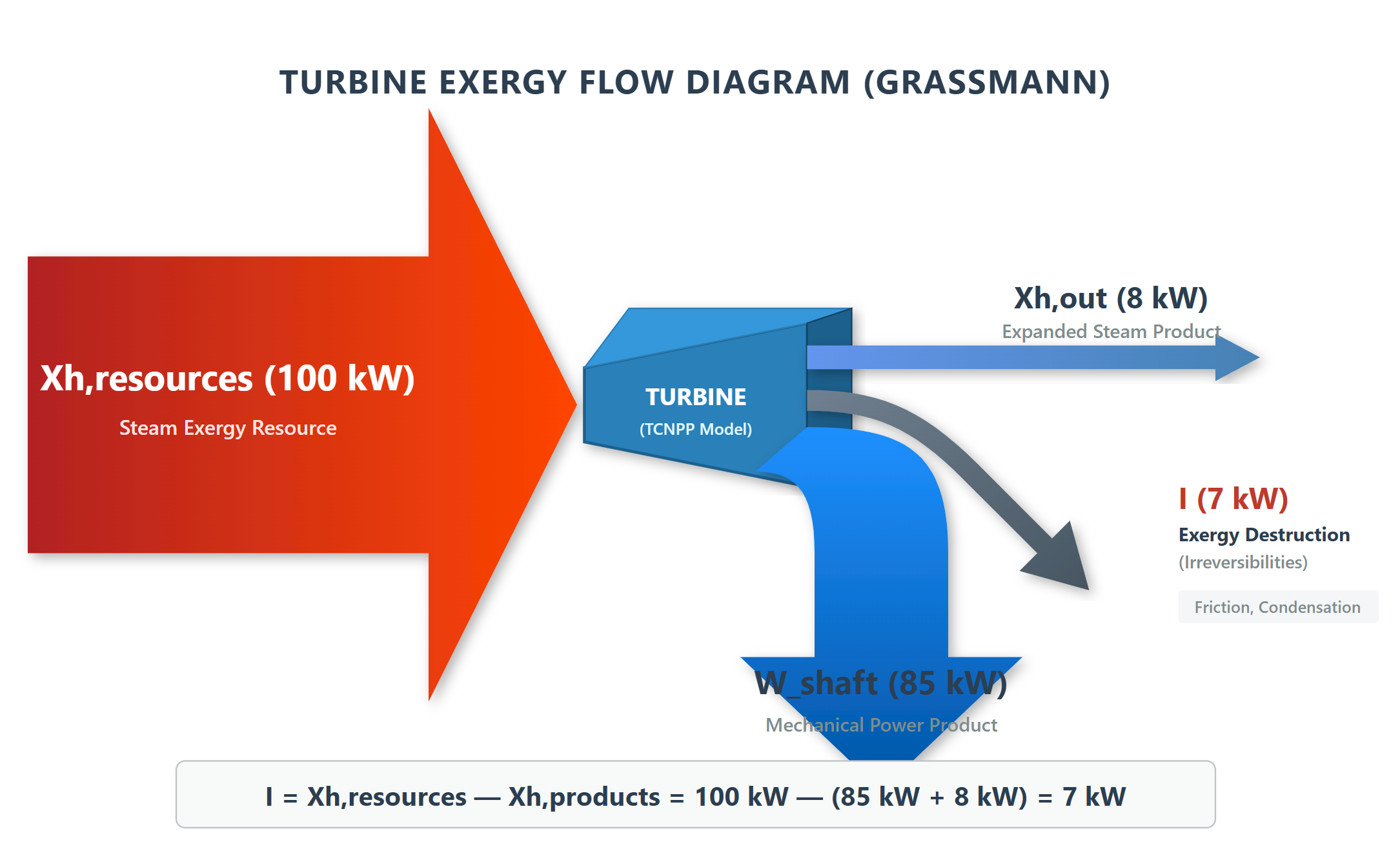
In a nuclear cycle, sources of irreversibility are present in every component:
🔴 Heat exchangers — Heat transfer between two fluids across a temperature difference generates entropy and destroys Xh. This applies to steam generators, feedwater heaters (FWH), and the intermediate sodium–sodium heat exchangers in Superphénix.
🟠 Turbines — Internal friction and partial condensation at low pressure reduce the recovered work compared to ideal isentropic work. In the ABWR, the LP turbines alone account for ~32 % of total irreversibilities.
🟡 Condenser — The heat rejected to the cold source (0.04 bar, ~29 °C) carries away a non-zero residual exergy.
🟢 Valves, pumps, mixers — Every component has its own specific irreversibilities. The throttling valve in the Canadian SCWR represents 5.2 % of total irreversibilities — a term invisible in an energy balance.
The sum of all these irreversibilities determines the overall exergetic efficiency η Xh. Across the 12 reactors analysed, this efficiency varies from 57.5 % (VVER-70 Nuscle model) to 73.9 % (EPR detailed model), reaching 71.9 % for the Canadian SCWR.
🟦 Productive and Dissipative Units (PDUs)
As illustrated by the turbine example above, analysing the exergy resources and products of a physical component reveals exergy flow connections that are structurally different from fluid flows.
While a turbine is crossed by a single fluid (steam), it receives one exergy flow and produces two outputs: mechanical power and the residual exergy of the downstream fluid.
👉 This leads to the concept of a Productive or Dissipative Unit (PDU).
PDUs enable the calculation of the exergy balance for each component. Each unit receives resources, which can be of three types:
- 🔴 Heat-exergy (from an external source at temperature Tk) or chemical exergy
- 🟠 Work
- 🟡 Exergy transferred by fluids flowing through the component
One or more products emerge from the unit:
- 🔴 Exergy variation of fluids flowing through the component
- 🟠 Work
Exergy receiver vs. exergy provider
The exergy of a fluid passing through a component can either decrease or increase:
- If it decreases (as in a turbine), the component is an exergy receiver — it takes exergy from the fluid and converts part of it into work.
- If it increases (as in a compressor or pump), the component is an exergy provider — it supplies exergy to the fluid using external work.
This figure shows an example of Productive and Dissipative Units (PDUs) in Thermoptim. The red box highlights the exergy provider (Reactor core and Compressor), while the blue box highlights the exergy receiver (Turbine and Cooler).
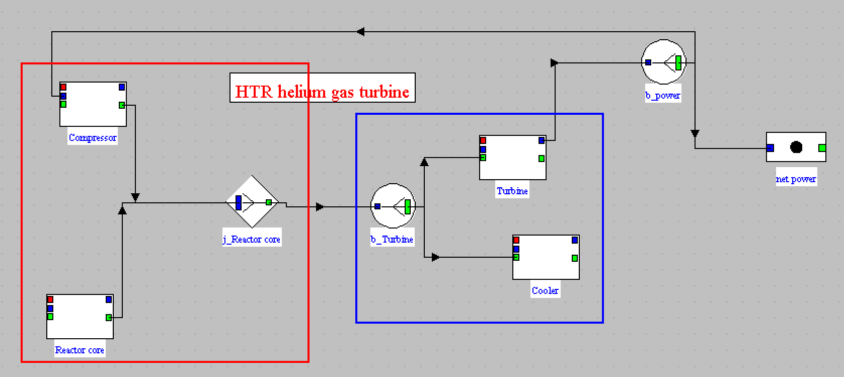
An exergy receiver is represented as a productive unit with a branch at the inlet, splitting the incoming exergy flow into two parts: the resource consumed by the component, and the residual exergy passed downstream.
An exergy provider is represented with a junction at the outlet, combining the inlet exergy flow and the work input into the total outlet exergy.
🟩 Representing Components as Productive Units in Thermoptim
In Thermoptim, each Productive Unit (PU) has a dedicated exergy balance screen that allows users to:
- Specify parameters for calculating exergy resources and products
- Determine irreversibilities
- Compute the exergy efficiency of the component
- Establish its complete exergy balance
Turbine example
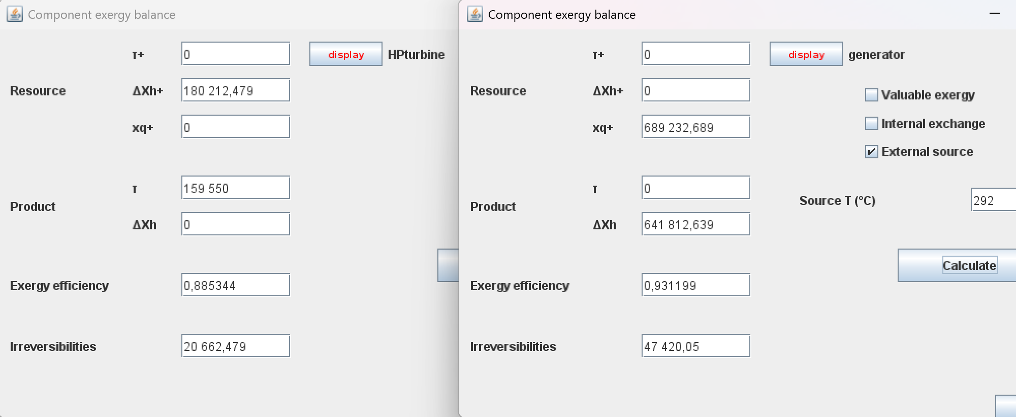
On the left side of this figure, the screen for a turbine component is shown. For a turbine, the exergy balance can be determined without specific parameterisation:
- Exergy resource: the exergy variation of the fluid flowing through it (ΔXh⁺)
- Product: the mechanical power (τ)
- Exergy efficiency and irreversibilities are directly derived
Heat exchange components
For heat exchange components, several configurations are possible:
- External heat source — When heat exchange occurs with an external energy source, the heat-exergy involved must be evaluated, requiring the source temperature Tk. This is how the reactor core is modelled in both the Nuscle WCR models and the detailed non-WCR models. As indicated on the right side of the figure, the exergy calculation screen includes an option to specify this situation (External source) and a field to enter the source temperature.
- Fluid inlet/outlet — Total exergy (physical + chemical) is taken into account. Exergy released to the environment is lost (irreversibility). If valued externally (e.g., cogeneration), it is an exergy product without irreversibility.
- Internal heat exchanges — For feedwater heaters and similar internal exchangers, the exergy loss equals, in absolute value, the sum of the exergy variations of the two fluids exchanging heat.
Throttling valves
For throttling processes, the exergy received is the total inlet exergy, the exergy provided is the total outlet exergy, and the irreversibility equals the difference. This is why the throttling valve in the SCWR — reducing pressure from 250 bar to the turbine inlet — accounts for a non-negligible fraction of the total irreversibilities.
👉 A table summarizing how the different types of Thermoptim core components are represented as PDUs is available for download.
🕸️ What is an Exergy Structure?
The graph obtained by connecting all the PDUs of a system together is called its exergy structure. It is a dual graph of the physical or functional diagram of the system.
The figure below (see book, Chapter 2) shows the correspondence between a classic simplified functional diagram of a steam power plant and the corresponding exergy structure:
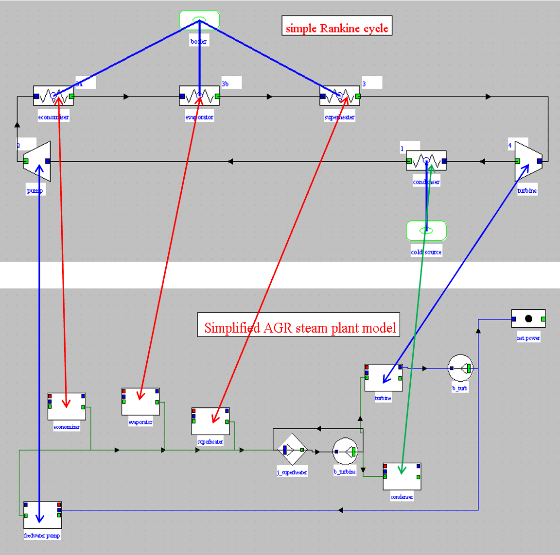
The steam power plant is a machine receiving an external exergy input in the boiler — corresponding to the productive units associated with the heat source at temperature Tk. Through internal recycling, exergy is also provided to the feedwater pump.
This exergy is partly converted into mechanical form in the turbine, and partly dissipated in the condenser. The net electrical power output is the fraction of mechanical power not recycled to internal auxiliaries.
Each component is associated with a productive or dissipative unit (UPD), and these are connected to each other either directly or via branches, according to the rules we mentioned previously.
This correspondence explains that it is possible to generate the exergy structure from the Thermoptim model and a small number of additional pieces of information.
💡 In Thermoptim, exergy structures are built automatically from the physical diagram, and the complete exergy balance for the entire system is computed and displayed without any manual calculation.
Regenerative gas turbine exergy structure
This is the regenerative gas turbine cycle which is the subject of guided exploration C-M2-V2.
The exergy structure is givent here:
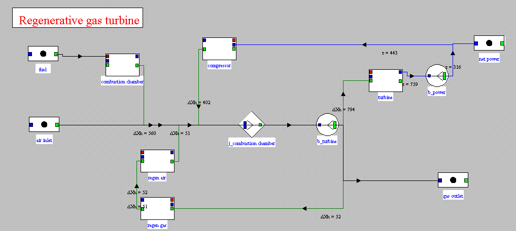
It is interpreted in the following way: the regenerative gas turbine is a machine which receives from the outside 560 kW of exergy in the combustion chamber, and, by internal recycling, on the one hand 402 kW of exergy from the compressor, and on the other hand 52 kW from the regenerator. This exergy is partly converted into mechanical form in the turbine (794 kW), partly returned to the regenerator (52 kW), and partly discharged to the outside (194 kW not readable in the figure). The net power corresponds to the fraction of mechanical power not recycled for the consumption of the compressor (316 kW).
You will note that the regenerator is represented by the two PDUs corresponding to the exchange processes that it connects.
The productive units representing the exchange processes of a heat exchanger are always linked together by a link intended to show the transfer of exergy which takes place within it.
Refrigeration machine exergy structure
This is the cycle of the refrigeration machine which is the subject of the guided exploration S-M3-V9.
The exergy structure is given here:
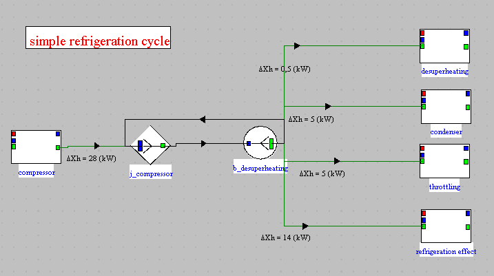
It can be interpreted as follows: the refrigeration machine receives an exergy supply from the outside in the compressor (28 kW). This exergy is partly converted in the evaporator (refrigeration effect, 14 kW), the rest being dissipated in the desuperheater (0.5 kW), the condenser (5 kW) and the expansion valve (throtlling, 5 kW).
What is an exergy balance?
An exergy balance is a table where the different PDUs appear in rows, with the following values in columns for each of them: the amount of its resources, its products, its own exergy efficiency, its irreversibilities, both in absolute terms and as a share of the total irreversibilities (in percentage), as well as a text field allowing certain points of its configuration to be specified. The last row corresponds to the complete system.
Exergy balances of simple cycles
For simple cycles, establishing an exergy balance poses no particular problem but needs to be done very carefully as otherwise errors can be committed.
Detailed methodological guidance is provided in this page of the Thermoptim-Unit portal. The Excel spreadsheet, downloadable given in this page, allows you, with some precautions, to reuse the Thermoptim results files.
In addition, Diapason session S06En, which deals specifically with the establishment of the exergy balances with a spreadsheet, will guide you through your first steps.
Exergy balances of complex cycles
An energy balance is conservative: what goes in equals what comes out, plus losses. This property allows errors to be easily detected.
Exergy does not have this property: it is destroyed in each irreversible component, and these destructions accumulate without being verifiable by simple looping. Therefore, drawing up an exergy balance by hand on a nuclear cycle with 20 to 40 components is a delicate operation, prone to errors, and difficult to validate.
Even when using the spreadsheet mentioned above, establishing the exergy balance of a somewhat complicated system can prove difficult in practice, because numerous modifications must be made to the spreadsheet.
Thermoptim provides a solution: its exergy structure and balance generation is fully automated from the thermodynamic model.
Each component is analyzed automatically, and the overall assessment is consistent with the energy balance by design.
Exergy balances generated using exergy structures
We have seen that exergy structures allow for a very clear graphical representation of exergy flows in an energy system.
To be able to automatically create an exergy structure in Thermoptim, you simply need to have a properly parameterized model of the system being studied, that is to say, its diagram and a project file. Once that is the case, the procedure to follow is as follows:
- open the editor of exergy structures by activating the corresponding line in the “Special” menu of the simulator
- then activate the line “Diagram transfer” of the “Special” menu of this editor
- suppress the nodes in series by activating the line “Suppression of nodes in excess” from the “Special” menu
- set the component energy balance screens
- connect PDUs that exchange mechanical energy
- rework the exergy structure to increase readability
All of these steps are explained step by step in this guided exploration: BESP-1: Exergy analysis and exergy structure of a simple steam cycle
It demonstrates how the exergy structure of a steam power plant cycle can be constructed and how it enables the calculation of the exergy balance of the modeled system.
If you wish to delve deeper into the subject, a second guided exploration follows. It reviews the exergy structures related to various cycles, each of which is presented in other guided explorations. BESP-2: Exergy balances and exergy structures of various cycles
- Regenerative gas turbine (EDC-M2-V2)
- Refrigeration machine (EDS-M3-V9)
- Steam cycle with reheating and extraction (EDC-M1-V5)
- Single-pressure combined cycle (EDC-M3-V1)
📊 Summary of Results
The table below gives the key results for all reactors analysed. Detailed balances and component-level breakdowns are presented in the pages listed below.
Detailed models (non-WCR + EPR reference):
| Reactor | Tk (°C) | η Xh | η energy | Source % | Condenser % | Turbines % |
|---|---|---|---|---|---|---|
| EPR Flamanville 3 | 334 | 73.9 % | 38.5 % | 30.0 % | 22.7 % | 32.2 % |
| Canadian SCWR | 670 | 68.5 % | 47.6 % | 51.9 % | 11.1 % | 20.1 % |
| CANDU Pickering | 292 | 68.4 % | 33.5 % | 24.1 % | 25.7 % | 36.7 % |
| RBMK-1000 | 324 | 65.2 % | 33.7 % | 30.1 % | 17.0 % | 38.2 % |
| Superphénix | 600 | 64.7 % | 43.3 % | 25.6 % | 16.0 % | 17.0 % |
| AGR Hartlepool | 699 | 61.8 % | 43.5 % | 37.3 % | 9.7 % | 18.1 % |
| HTR-PM | 624 | 59.2 % | — | 42.4 % | 9.7 % | 17.6 % |
Nuscle models (WCR — η structurally lower than detailed models):
| Reactor | Tk (°C) | η Xh | η energy | Source % | Condenser % | Turbines % |
|---|---|---|---|---|---|---|
| VVER-1000 | 313 | 68.0 % | 34.6 % | 22.0 % | 18.3 % | 44.4 % |
| RBMK-1000 | 324 | 67.2 % | 34.8 % | 28.6 % | 17.5 % | 37.0 % |
| EPR Flamanville 3 | 335 | 65.8 % | 34.6 % | 22.7 % | 18.6 % | 39.5 % |
| CANDU Pickering | 292 | 63.6 % | 31.2 % | 24.1 % | 20.5 % | 43.1 % |
| NuScale US600 | 335 | 63.4 % | 33.4 % | 48.3 % | 16.4 % | 26.1 % |
| ABWR | 330 | 62.3 % | 32.5 % | 20.3 % | 18.7 % | 40.5 % |
| VVER-70 | 283 | 57.5 % | 27.7 % | 39.4 % | 19.2 % | 36.6 % |
| NuScale US460 (77 MWe) | 335 | 52.3 % | 27.5 % | 51.1 % | 22.2 % | 24.6 % |
Source = ‘generator’ + ’economizer’ in Nuscle models. η energy = net electrical output / thermal power input Q_th.
📚 Pages in This Section
| Page | Content | Status |
|---|---|---|
| Fundamental Concepts | Energy vs exergy, irreversibilities, productive units, exergy structures | ✅ Available |
| Using Exergy Balances | How to read a balance, optimisation guidance, source temperature effects | ✅ Available |
| Detailed Models — Component Analysis | Component-by-component analysis: EPR, AGR, SPX, SCWR, CANDU, RBMK, HTR | 🔜 Coming soon |
| Nuscle Models — WCR Comparison | Cross-reactor comparison using Nuscle; pedagogical use of simplified models | 🔜 Coming soon |
| Cogeneration and Exergy | The thermodynamic case for nuclear cogeneration | 🔜 Coming soon |
The exergy analysis in this section is based on models and results first presented on LinkedIn as part of the book’s companion publication series.